Posted: October 19, 2004
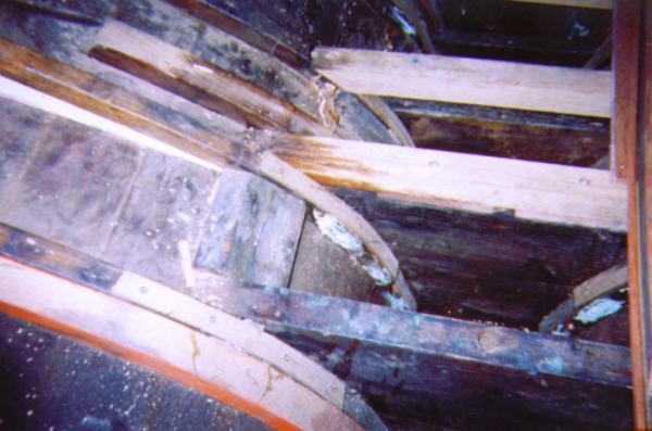 |
1. CHELSEA’s bilge has been absolutely dry for the past 4 years. DRY AS A BONE in the desert. In the winter storms of 2003/04 she rocked so severely in her berth that bilge seams opened up. The inevitable task was at hand. The sole needed to be pulled up and the fuel tank removed to discover the cause. The painful truth can be seen in this photo taken after we had done much of the repair work. EVERY RIB from the mast step to the engine compartment bulkhead was cracked. The cracks were very old and had been sistered with some very puny sisters very long ago. |
 |
2. Not only were there cracks, but the galvanized bolts fastening the ribs to the floors were rusted memories, and the floors suffered from iron sickness. So, what we did was over bore the holes after driving out the rust. Then we epoxied in dowels to seal these holes. Next, we used silicone bronze bolts to re-fasten the floors to the ribs and newly installed, sawn sisters. This view is from the salon area toward the mast step. |
 |
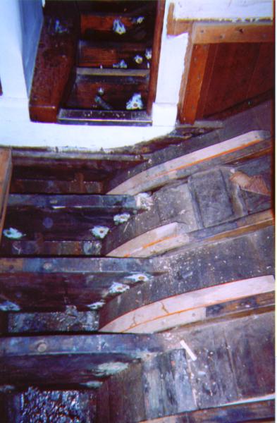
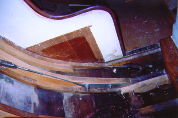
3. The decision was made not to re-install the monel fuel tank and use a bladder instead. Someday the next owner of CHELSEA can re-rib her completely. For now and for the next 20 years her new, white oak, sawn sisters will have to suffice. Accordingly, she needed some struts to hold up the sole in the cabin. That’s what you see here. These struts have been placed on top of the ribs rather than resting on the planks. |
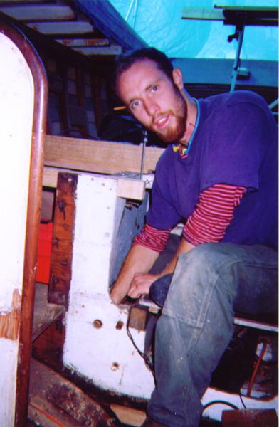 |
4. So we now turned our attention to the galley, cabin-companionway bulkhead and sub-structure of the cockpit. First, the neglect had brought on rot to the bulkheads; so we removed them a couple of years ago and installed some temporary patterns for sleepover purposes. Second, the sub-structure for the bulkhead and cockpit sole had been dramatically altered to make room for the 3 cylinder Isuzu diesel which caused all the problems in the first place (read the early installments in this saga about the transom replacement); and Third, the rats nest that the icebox had been turned into brought some rot to the struts holding up the galley step crossmembers. This is a photo of the very, very skilled Boatwright, Casey Nutt taking on the work you see in this series of photos about the sisters in the bilge, the sub-structure replacement, and the "jockstrap". Casey spent over one year studying at the Port Townsend School of Wooden Boat Building and has been studying under the tutelidge of our other very skilled and wise Boatwright, David Cassie. |
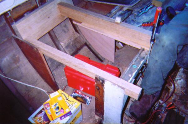 |
5.The cross members, both fore/aft and athwarts, supporting the cockpit sole, companionway steps, and cabin bulkhead were cut in order to accommodate that damn 3 cyl. Isuzu motor!!! So they have to be replaced in order to give the boat back her structural integrity and support all the features listed. The single design feature that we will incorporate will be to enable the center sections of the athwarts support members to be removed for access. |
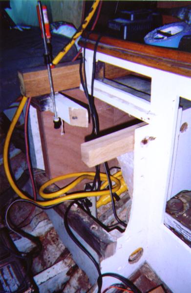 |
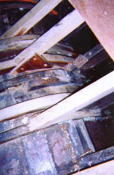
6. See the clamp? It is holding the new, companionway/bulkhead cross member to the fore/aft/ cockpit support. Both had been cut by whomever installed that damn motor. Right behind this you can see one of two quarter bulkheads Casey has installed to even further support the cockpit sole. |
 |
7. The athwarts cross members were supported at either end by 1x2 strips of pine nailed to the ribs. Casey has fashioned a support out of white oak to support them instead. This custom fit piece has sockets to receive the cross members and is screwed to three ribs each. |
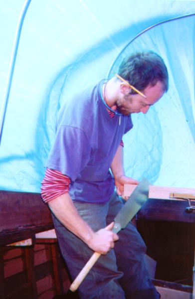 |
8. Here’s another picture of Casey cutting an angle into a piece of white oak for scarfing onto one of the old fore/aft cockpit sole supports. |
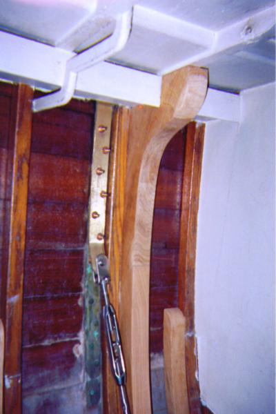 |
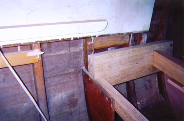
9. So, we also thought that since the bilge was so wide open we’d improve upon the technology of the K-38 and transfer the stress from the shrouds to the keel via a new method rather than rely upon the ribs and planks alone. Casey fashioned a "jock strap" that consists of a custom built rib which goes from the port shear clamp to the starboard shear clamp. Here you can see the upper end of the new rib, an additional chain plate with a turn buckle attached. |
 |
10. The turn buckle transfers stress from the chain plate to a stainless steel “floor” whick is bolted to a new oak floor in the bilge. |
 |
11. This stainless steel floor transfers the stress to the keel via the oak floor and continues on over to the other side to accept the eye and wire rope from the chain plate assembly on that side. |
 |
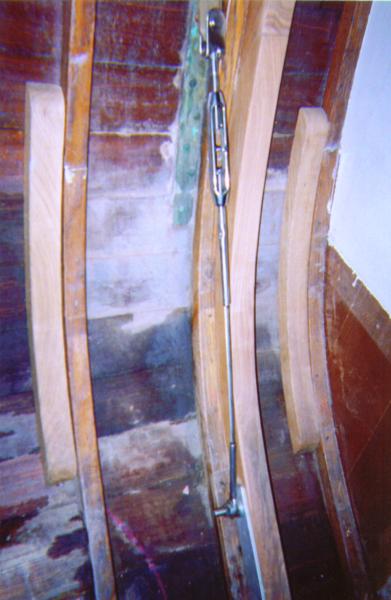
12. In photo 9 you see the new structure on the Starboard side. Here is a photo of this new feature as seen in the head or port side. This picture was taken from the doorway to the head. Casey is justifiably proud of this work. So am I. It will do a lot to add to the structural integrity of my 50 year old K-38, CHELSEA. |